Learning Software Architecture by Building a Cocktail Machine
This is part 1 of a three-part series about building NEAT, my DIY cocktail machine. In this article, I'll focus on the software architecture and what I learned while designing it.
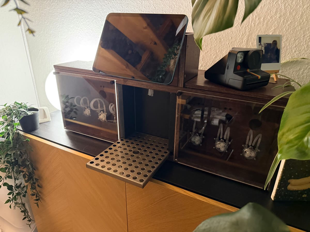
When I started building my cocktail machine, I could have just written a prompt to generate some code to control a few pumps and called it a day. But I wanted to use the project as an opportunity to learn more about software architecture.
The machine itself is relatively simple: A user selects a cocktail on an iPad, and an ESP32 controls six pumps to dispense the required ingredients.
However, once I started thinking about recipes, calibration, sensors, error handling, and communication between the frontend and the controller, I realized there was more to it than just switching GPIO pins.
Starting with requirements and use cases
Before implementing the actual machine logic, I started documenting what the system needed to do.
I wrote functional and non-functional requirements, use cases, and constraints.
For example:
- Functional requirement: The machine should be able to dispense a specified amount of an ingredient.
- Non-functional requirement: The machine should work without an internet connection.
- Constraint: The current hardware has six pumps, which limits the number of ingredients that can be connected simultaneously.
- Use case: A user selects a cocktail, the machine verifies that the required ingredients are available, checks for a glass, and starts preparing the drink.
The interesting part was thinking about everything that could go wrong. What happens when there is no glass? What if a pump hasn't been calibrated? What if a required ingredient isn't connected?
I found it useful to think about these questions before writing the corresponding code.
Modeling the domain
Next, I created a domain model to describe the important concepts and how they relate to each other.
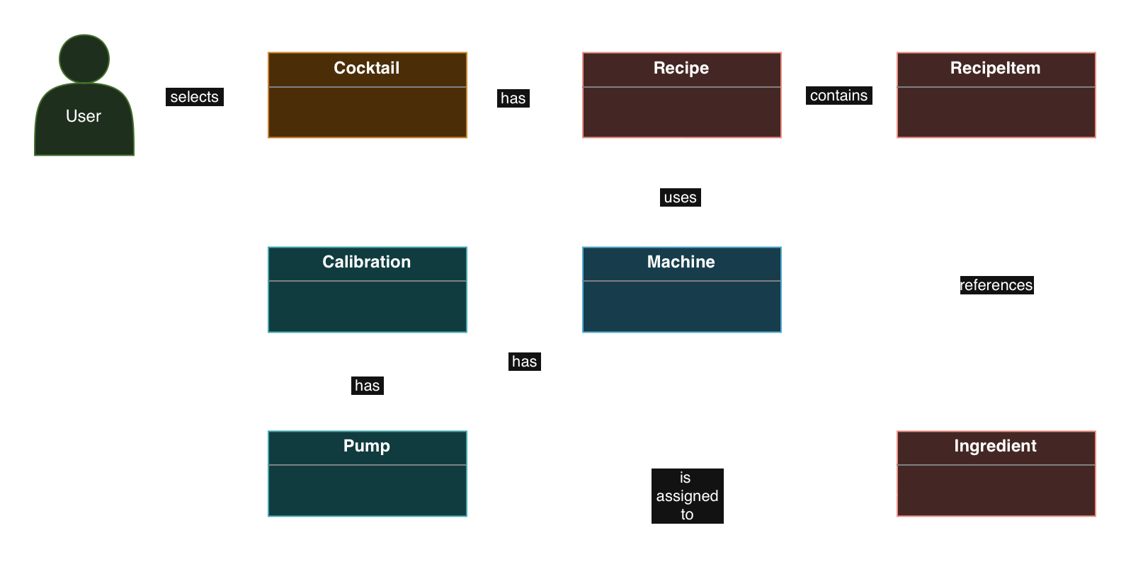
For example, a Cocktail has a Recipe, which contains multiple RecipeItems. Each item references an Ingredient, while the machine has pumps that can be assigned to those ingredients.
I also modeled Calibration separately because every pump can have a slightly different flow rate.
This helped me distinguish between the actual cocktail recipes and the hardware configuration. A recipe shouldn't need to know which physical pump contains vodka.
Documenting the architecture with C4
I then started learning about the C4 model, which describes a software system at different levels of abstraction.
Instead of creating one enormous diagram, I could start with the overall system and gradually zoom into the implementation.
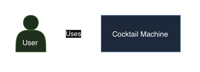
The System Context Diagram shows the cocktail machine and its user, without any unnecessary implementation details.
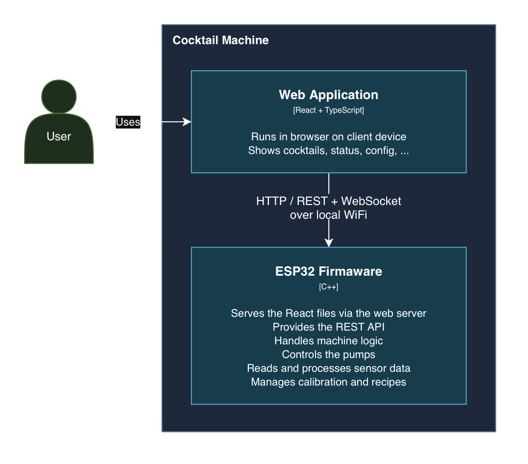
The Container Diagram introduces the two main software parts: a React and TypeScript web application running on the iPad and the ESP32 firmware written in C++. They communicate over local Wi-Fi using REST and WebSockets.
Finally, the Component Diagram shows the internal structure of the firmware, including components such as MachineLogic, PumpControl, SensorHandling, and the API interface.
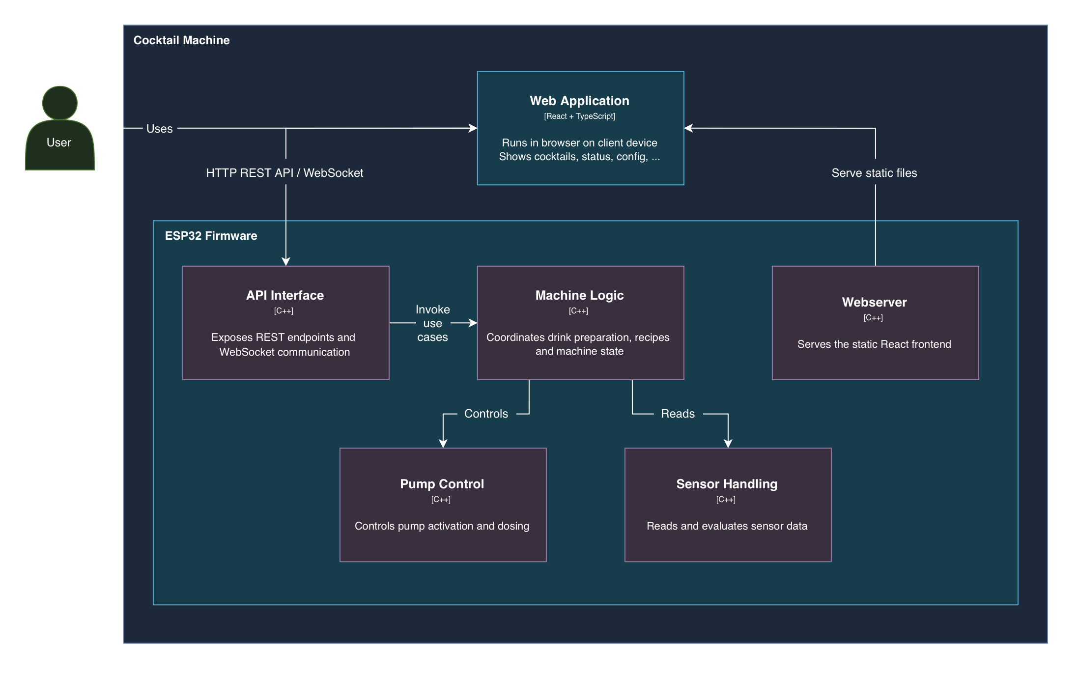
I liked how each diagram answered a different question without becoming unnecessarily complicated.
When my UML class diagram became too complicated
I also created a traditional UML class diagram showing the relationships between the individual classes.
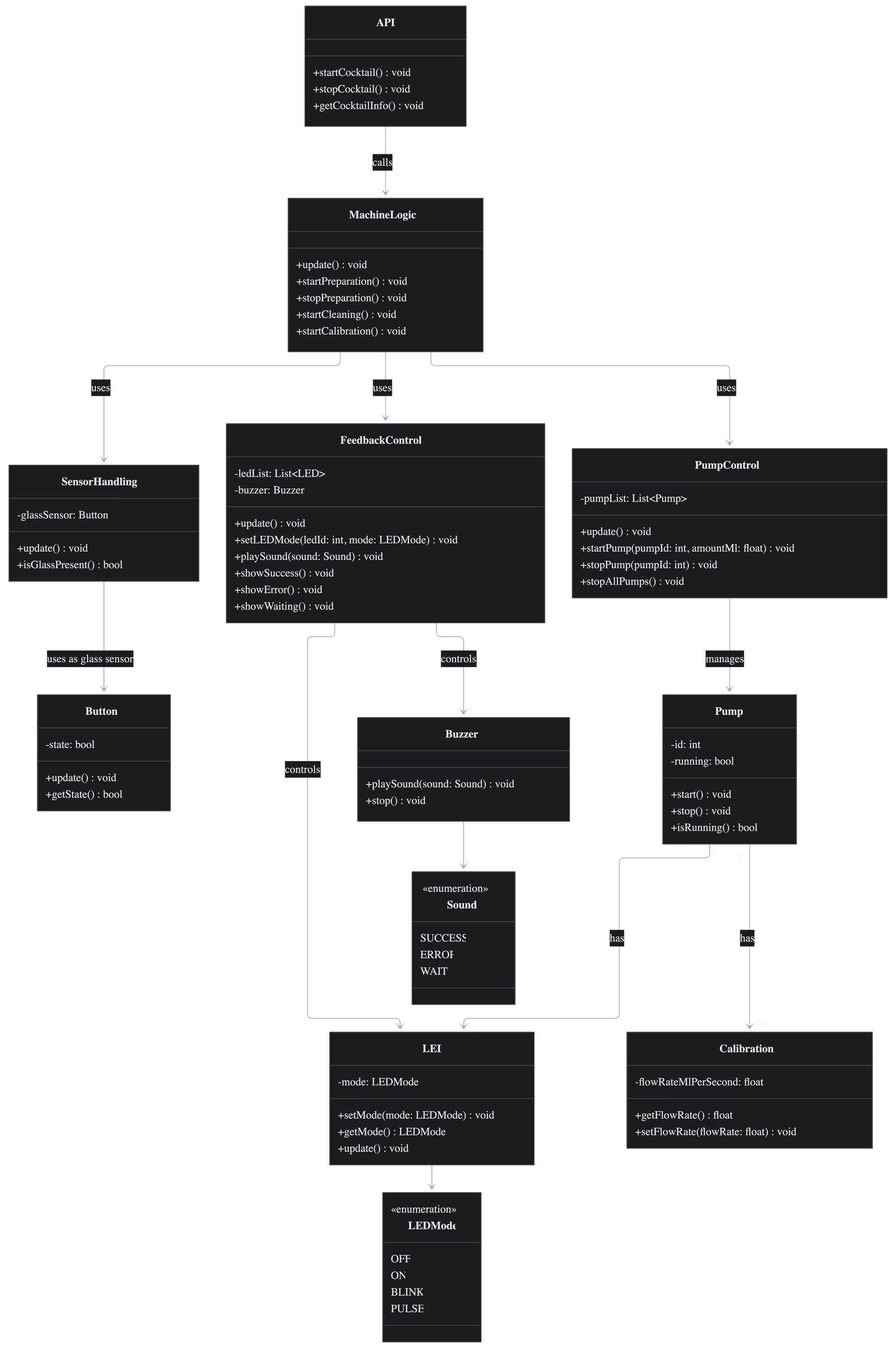
Initially, it was useful. But as I added more functionality, the diagram kept growing.
Eventually, I realized that maintaining one large class diagram for the entire project wasn't particularly helpful anymore. It was becoming difficult to read, and every architectural change meant updating yet another part of the diagram.
That was one of the more useful things I learned: Documentation should make a system easier to understand, not become another problem to maintain.
I still think class diagrams are useful, but I'd rather use smaller ones for specific components instead of trying to document the entire codebase in one place.
Modeling behavior and documenting decisions
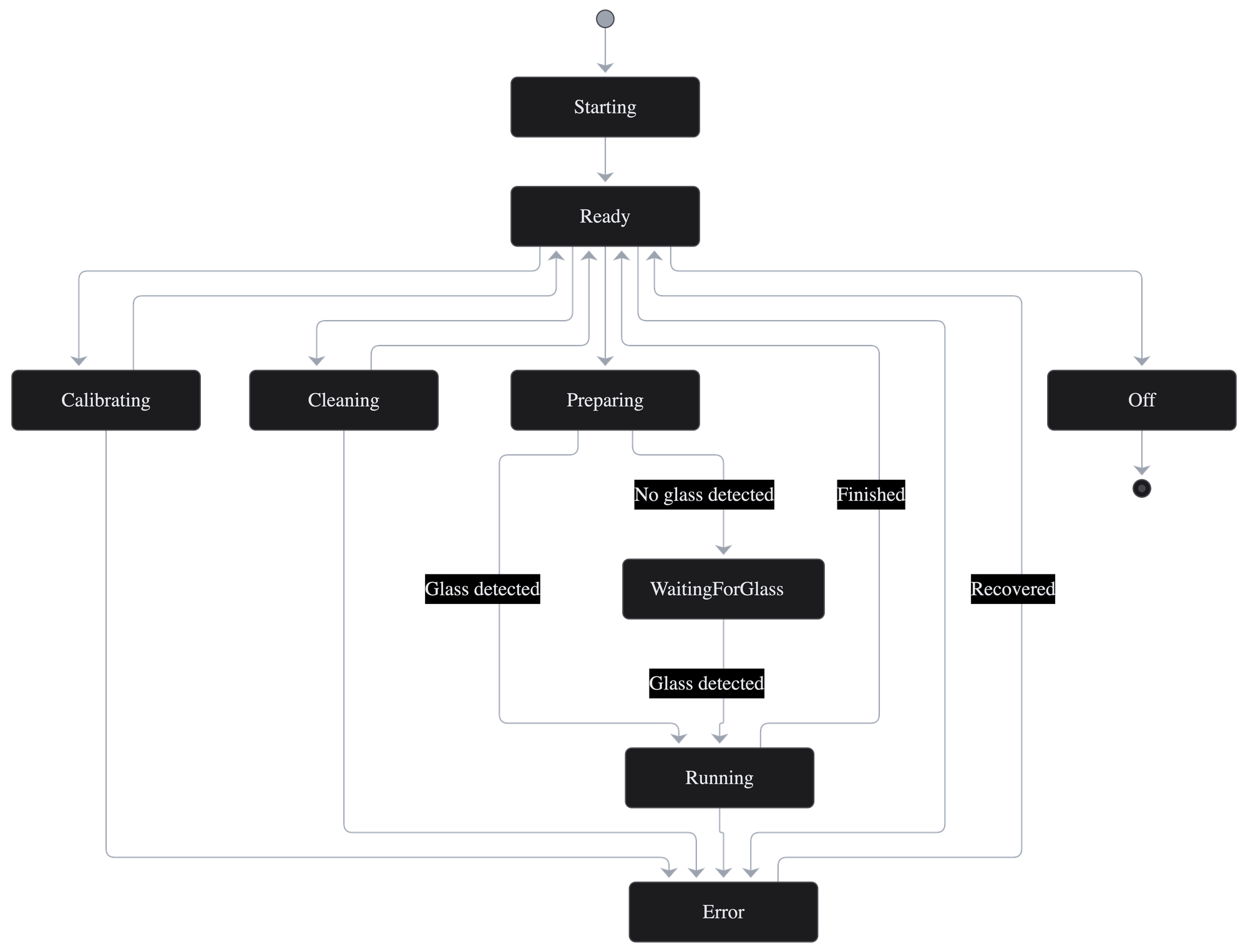
Besides the structural diagrams, I created a state machine diagram showing states such as Ready, Preparing, WaitingForGlass, Running, Cleaning, and Error.
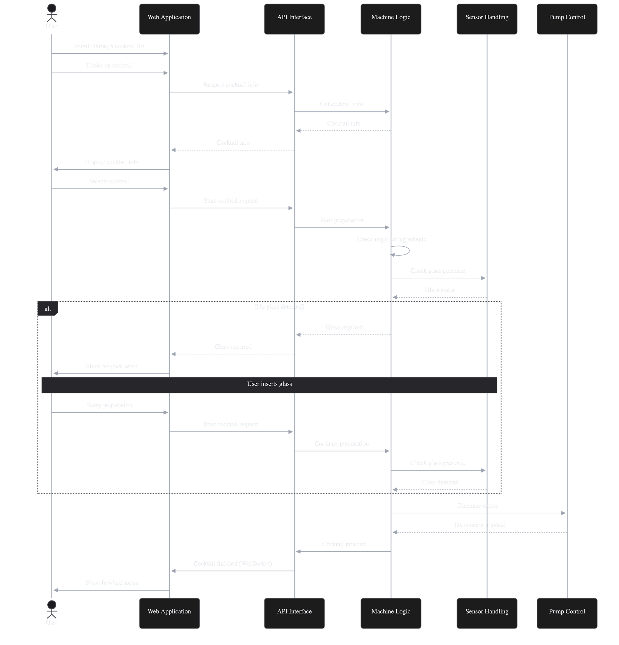
I also created a sequence diagram illustrating how the frontend, API, machine logic, sensors, and pumps are supposed to interact during cocktail preparation.
Another technique I started using was Architecture Decision Records (ADRs). These document architectural decisions, the reasoning behind them, and their consequences.
One example is the decision to make the machine work locally, without requiring an external server. This simplifies using the machine in different locations, but means the ESP32 needs to handle the API and serve the frontend while also controlling the hardware.
What I learned
The biggest takeaway for me wasn't a specific diagram or design pattern.
It was learning to think about the responsibilities of individual components, the relationships between them, and the consequences of architectural decisions before implementing everything.
I definitely spent more time planning than would have been strictly necessary to make six pumps run. But that was also part of the point: I wanted to learn how to design and document a system properly.
This article is part of the three-part Building NEAT series. Part 2 covers the ESP32 prototype, pump control, and electronics.
